"DISEÑAMOS LUJO, CONSTRUIMOS TU HOGAR"
Tips for laying your home's foundation
We'll tell you about the preliminary steps you must follow before starting to pour the concrete for a foundation.
Arq. César H. Germán Carrillo
10/7/202517 min read
The foundation isn't just concrete and steel; it is the most critical part of any structure, as it transfers the loads of the entire building to the underlying soil. A meticulous preliminary design is your house's insurance policy. Skipping this process is, literally, building on sand. The design is based on two fundamental pillars: understanding the soil and calculating the loads.
1. The Geotechnical Pillar: Knowing the Soil
Design cannot begin until we know what lies beneath the construction site. This is achieved through the Soil Mechanics (Geotechnical) Study, which is not a cost but an essential investment.
What the Soil Study Reveals:
Bearing Capacity: This is the measure of the maximum pressure the soil can support without failing or experiencing excessive settlement. Soil with low bearing capacity will require a wider or deeper foundation to distribute the weight.
Water Table (Nivel Freático): Determines the presence of groundwater. A high water table may require costly pumping systems during construction or a special design to prevent steel corrosion and the loss of bearing capacity in saturated soil.
Soil Composition: Identifies whether the subsoil is rock, expansive clay (which swells with water), sand, or silt. Each type requires a distinct foundation approach. For instance, expansive clays are highly problematic and may need deep foundations or floating slabs.
Seismic Risk: In earthquake-prone areas, the study evaluates the soil's susceptibility to liquefaction, a phenomenon where saturated sandy soils lose strength due to vibrations.
2. The Structural Pillar: Calculating the Loads
Once the soil's strength is known, the structural engineer must calculate how much weight the house will exert upon it. These are the "loads" that the foundation must support and distribute:
Dead Loads: The fixed weight of the structure itself: walls, roofs, slabs, finishes, and the weight of the foundation itself.
Live Loads: The variable weight based on use: people, furniture, appliances, and snow or rainwater loads.
Accidental Loads: Unpredictable forces such as wind and seismic forces (earthquakes). These are crucial and often the forces that demand the most reinforcement in the design.
3. Design Decision: Choosing the Foundation Type
With the soil data and loads in hand, the most appropriate type of foundation is chosen. They are mainly classified into two categories:
a. Shallow Foundations (The Most Common Option) Used when load-bearing soil is found at a shallow depth (generally less than 4 meters, or about 13 feet).
Isolated Footings: Placed under individual columns to support point loads.
Strip Footings (Continuous Footings): Continuous strips of foundation that support load-bearing walls.
Mat or Raft Foundations (Slabs): A concrete slab that covers the entire footprint of the building. It is used when the soil's bearing capacity is low or when the structure's load is very high, as it distributes the weight over a maximum area.
b. Deep Foundations Required when the surface soil is very weak or compressible and the resistant stratum is located at great depths.
Piles or Piers: Columns that are driven or excavated until they reach a firmer layer of soil or rock, transmitting the load through end-bearing and/or lateral friction.
4. The Final Design: Dimensioning and Reinforcement
The design culminates in the exact dimensioning of the elements. This includes:
Dimensioning: The height, width, and depth of the footings or slab are calculated. The size is directly proportional to the load and the need to reduce pressure on the soil.
Steel Reinforcement (Rebar): Concrete is very strong in compression (when crushed) but weak in tension (when stretched). The steel reinforcement (rebar) is strategically placed to absorb these tensile forces and ensure the foundation's ductility, which is especially important in seismic zones.
Protection and Drainage: The design must include concrete waterproofing to protect it from moisture and, often, a perimeter drainage system that diverts water away from the base of the house, preventing soil saturation and the risk of frost damage.
The preliminary foundation design is an engineering process that integrates site geology with structural engineering. It is the phase where you invest in the safety and longevity of the entire building.
Preliminary foundation design: the basis of every safe project


The site preparation phase is the transition between the design blueprint and the physical reality of the construction work. At this stage, the exact dimensions of the structure are defined on-site, and the ground is prepared to receive the foundation.
1. Clearing and Site Stripping
The first task is to ensure the construction area is completely cleared and free of any elements that could interfere with excavation or affect the stability of the future foundation.
Obstacle Removal: Trees, shrubs, weeds, surface rocks, and any organic material are removed.
Demolition (If Applicable): If there are old structures or remnants of previous constructions, they must be completely demolished and removed.
Importance: The presence of organic material (such as roots or buried logs) is critical. Over time, these materials decompose, creating voids and settlements that could cause cracks or failures in the foundation. It is essential to remove the entire superficial layer of topsoil (vegetal soil).
2. Foundation Layout and Setting Out
Layout (Setting out or Staking out) is the process of transferring the foundation dimensions and location from the blueprints to the actual ground. It is the precise materialization of the structure's axes.
Fixed Reference Points: Reference points (or benchmarks / monuments) are established outside the excavation area. These must remain immovable throughout the construction process and serve to re-establish the axes if the markings are erased.
The 3-4-5 Method: To ensure all foundation angles are perfectly square (90∘), the Pythagorean theorem (a2+b2=c2) is used in the well-known 3-4-5 method.
Batter Boards (Reference Fences): Wooden fences are constructed outside the limits of the excavation. On these boards, stakes are driven or the exact axes of the walls and footings are marked, using strings or cords to delimit the perimeter.
Precision: An error in the layout is multiplied in the structure above. A poorly laid-out foundation will result in misaligned walls.
3. Site Grading and Leveling
Leveling (Grading) aims to establish the reference elevation (height) of the construction. In most cases, the goal is to set the finished floor of the house slightly higher than the surrounding terrain to prevent flooding and ensure proper drainage.
Determining the Benchmark (BM) Level: A fixed point (the sidewalk, a corner of a neighboring building, or a special stake) is chosen as the 0.00 reference point.
Use of Instruments: Bubble levels, water levels (hose levels), or, in larger projects, laser or surveying levels (total stations) are used to transfer this reference elevation across the entire surface.
Working Surface: The ground is leveled as much as possible before digging to facilitate a uniform depth for the trenches and ensure that the foundation bases are all at the same structural height.
4. The Excavation
Once the location and levels are perfectly defined, the earthwork begins to open the trenches or pits that will receive the concrete.
Manual vs. Mechanical Excavation: The choice depends on the volume of soil, the soil hardness, and accessibility. In residential construction, machinery is often used for general excavation, and manual labor is used to finish the bottom surfaces of the trenches.
Minimum Depth: The excavation must reach the depth determined by the structural design, which ensures reaching a soil layer with the necessary bearing capacity. Furthermore, it must be dug below the frost line (in cold climates) to prevent the expansion of frozen soil from lifting the foundation.
Trench Bottom: It is crucial that the bottom of the trench or footing pit is firm, horizontal, and undisturbed. If the bottom loosens or becomes saturated with water, that material must be removed and refilled with a compactable, granular material, or else dug deeper to find stable ground.
Slopes and Safety: In deep excavations, slopes (lateral inclination) must be considered to prevent cave-ins. Safety is paramount; it is necessary to shore up (or brace) the excavation walls if there is a risk of collapse.
Once the excavation is ready, clean, and approved by the supervisor, the next step is to place the lean concrete blinding layer (mud slab or sub-base), which serves as a clean and level base for the placement of the final foundation's steel reinforcement.
Clearing, layout, leveling, and excavation
Ground improvement, or soil stabilization, is applied when the geotechnical study reveals that the surface soil has low bearing capacity, is highly compressible (prone to settlement), or is susceptible to moisture (such as expansive clays). The objective is to increase the soil's strength and stiffness to prevent failure, deformation, or excessive settlement of the structure.
1. Common Superficial Improvement Methods
These methods focus on the upper layers of the ground and are the most common in single-family housing projects.
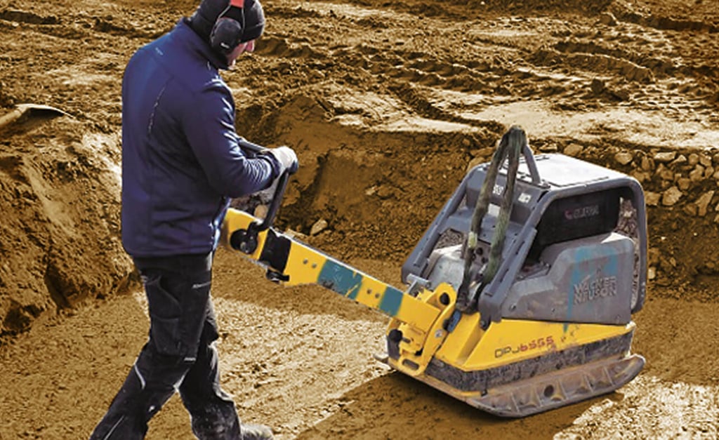
a. Dynamic Compaction and Controlled Fill
The most basic and frequent method is to ensure adequate density and bearing capacity through compaction.
Removal of Unsuitable Material (Soft Soils): If the top layer is topsoil or soft organic material, it must be completely removed until a firmer stratum is reached.
Backfill and Compaction: The excavated area is refilled with granular borrow material (gravels, sands, or select quarry material) which is less sensitive to moisture than clays. This material is placed in thin layers (20 to 30 cm or 8 to 12 inches) and compacted with vibratory machinery (compactors or rollers) until a specific compaction percentage is achieved (generally between 90% and 95% of the standard Proctor).
Importance: Proper compaction increases density and decreases porosity, which enhances the bearing capacity and reduces future settlements.
b. Soil Replacement (Substitution)
This is used when the soft material extends to a manageable depth. It involves excavating all the inadequate material and substituting it with high-quality, well-draining fill material (such as sand or gravel). It is a direct method but can be costly if the depths are great.
2. Stabilization Methods by Material Addition
These methods alter the physical-chemical properties of the soil to improve its behavior.
a. Stabilization with Lime
This is mainly applied to clay soils (fine soils that change significantly with moisture).
Process: Quicklime or hydrated lime is mixed with the soil on-site. The lime chemically reacts with the clays, reducing their plasticity and their tendency to expand and contract with changes in moisture.
Benefit: It makes the soil more workable, stronger, and less moisture-sensitive, improving the subgrade (the prepared surface) before pouring the foundation.
b. Stabilization with Cement
Similar to the process with lime, Portland cement is used to create a soil-cement.
Process: Cement is mixed with the soil (typically silty or sandy) and water. Upon curing, the cement binds the soil particles together, forming a stiffer and more resistant material.
Benefit: It significantly increases the compressive strength and is ideal for creating very firm bases.
3. Improvement for Deep Foundations (Uncommon in Housing)
While less frequent in small homes, if the problematic soil is very deep, more advanced techniques are used to transfer the load to more resistant strata.
Stone Columns (or Aggregate Piers): Shafts are excavated and refilled with highly compacted gravel. These columns act as short, stiff pillars that densify the surrounding soil and help dissipate excess pore pressure (water).
Preloading or Consolidation: This is used for very compressible soils (like silts or soft clays). It involves placing a large mass of material over the construction site for a period of time (months). The weight of the preload squeezes water out of the soil, accelerating the natural settlement before building the actual house, thus preventing the settlement from occurring under the finished structure.
Final Considerations
The ground improvement method must always be specified and supervised by a civil or geotechnical engineer. Correct execution is verified by laboratory and field tests (such as the field density test) to confirm that the improved soil has achieved the strength and stability required by the structural design. Poorly executed improvement is as risky as not doing it at all.
Ground Improvement
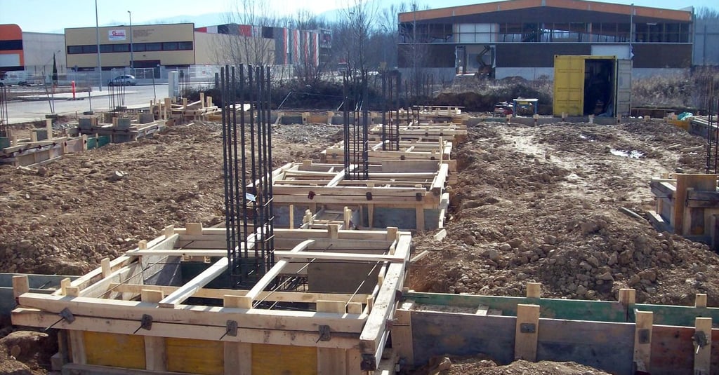
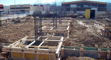
Placing formwork
Formwork (also known as falsework or shuttering) is the temporary structure that acts as a mold to contain and shape fresh concrete until it cures and gains sufficient strength. In house foundations, proper formwork is paramount to ensure the footings (zapatas) and grade beams (contratrabes) have the correct dimensions, levels, and alignment specified in the structural plans.
1. Materials and Preparation
The formwork must be robust enough to withstand the significant pressure exerted by fresh concrete.
A. Common Materials
For residential foundations, the most common type is timber formwork.
Lumber and Plywood: Boards, planks, and plywood sheets are cut to the exact dimensions of the foundation elements. This is favored for its cost-effectiveness, flexibility for custom shapes, and ease of assembly/disassembly.
Metal Forms: Pre-fabricated steel or aluminum panels may be used for large, repetitive, or strictly linear elements, offering higher precision and reusability, but at a higher initial cost.
B. Pre-Pour Essentials
Before any formwork is placed, the ground must be ready:
Trench Approval: The trenches must be at the correct depth, clean, and firm.
Slab/Blinding Layer (Plantilla): A thin layer of lean concrete (non-structural concrete) is poured at the bottom of the excavation. This layer provides a clean, level, and dry surface for the steel reinforcement and ensures the structural concrete doesn't lose moisture to the soil.
2. Assembly and Bracing (The Critical Step)
The formwork is assembled piece by piece, ensuring it aligns precisely with the construction layout established during the initial layout and staking (trazo) phase.
A. Alignment and Leveling
Using Layout Lines: The formwork boards are placed along the layout lines (string lines or laser marks) that define the exact edges of the footing or grade beam.
Establishing the Top Elevation: A water level or laser level is used to mark the precise top elevation of the pour inside the forms. This mark ensures that the foundation surface is perfectly horizontal and at the specified structural height.
B. Bracing and Support
Since fresh concrete exerts high lateral pressure (hydrostatic pressure), the formwork must be heavily supported:
Stakes and Kickers: Wood stakes are driven firmly into the ground outside the forms. Kickers (diagonal braces) are then installed from the stakes to the sides of the formwork.
Waler/Studs: Horizontal members (called walers or studs) are often placed on the exterior side of the vertical form boards to reinforce them and distribute the pressure evenly across the bracing system.
Tie Wires/Bolts: For deep forms, tie wires or through-bolts may be run across the interior of the mold to resist outward pressure. Crucially, these must not interfere with the rebar cage.
3. Preparing for Concrete and Stripping
Once the formwork is set, the process shifts to protecting the concrete and preparing for removal.
A. Rebar Placement and Inspection
The steel reinforcement cage is placed inside the secured forms. Before pouring, an inspection must confirm:
Correct Rebar Position: The steel matches the structural drawings.
Adequate Cover: Spacers or chairs (small concrete blocks or plastic clips) are used to lift the rebar cage off the blinding layer and away from the sides of the formwork. This minimum cover protects the steel from corrosion.
B. Applying Release Agent
A form release agent (typically a special oil or chemical) must be applied to the interior face of the formwork.
Purpose: It prevents the concrete from bonding with the form material, allowing for easy and clean stripping (descimbrado) without damaging the finished concrete surface.
C. Stripping the Forms (Descimbrado)
Formwork must be removed carefully and only once the concrete has gained sufficient strength to support itself.
Foundation Walls/Footing Sides: Lateral forms can usually be removed after 24 to 48 hours, as they are non-load-bearing.
Beams/Slabs: For formwork supporting a structural element from below (like shoring under a suspended slab), removal times are much longer (often 7 to 28 days), dictated by the design specifications and concrete strength tests. Premature stripping risks collapse and structural failure.
Moisture protection
Moisture can attack a house's foundation in three main ways: by capillarity (rising from the soil), by lateral filtration (water pushing from the exterior), and by inadequate drainage (accumulated surface water). The protection strategy must be comprehensive, addressing all three fronts.
1. Primary Barrier: Waterproofing (or Damp-Proofing)
This is the direct defense applied to the concrete surfaces of the foundation that are in contact with the soil.
a. Foundation Walls and Grade Beams
Once the concrete has cured and the formwork (cimbra) has been removed, it is crucial to protect the vertical and horizontal elements from ground moisture.
Asphalt Membranes (Emulsions): Layers of bituminous (asphaltic) products are applied either cold or hot directly onto the exterior surface of the foundation wall. They form a continuous, impermeable layer.
Prefabricated Membranes: These are sheets (usually of modified asphalt or polymers like HDPE) that are adhered to or draped over the wall. They offer a more uniform barrier and a guaranteed thickness.
Cementitious Waterproofing Mortars: These are mixtures that contain chemical additives. They are applied as a render coat and react to block the pores in the concrete, making it impermeable.
b. Barrier Against Rising Damp (Capillarity)
To prevent water from climbing through the concrete's pores into the upper walls of the house (a phenomenon known as rising damp or capillarity):
A horizontal barrier (such as plastic sheeting or bituminous membranes) is placed just atop the foundation and beneath the first course of masonry (blockwork/brickwork). This interrupts the water's upward path.
In the floor slab, heavy-gauge polyethylene sheeting is placed directly over the gravel bed (if any) and beneath the concrete of the slab.
2. Perimeter Drainage: The Defense Against Hydrostatic Pressure
The best way to protect a foundation is not just to block water, but to prevent water from accumulating and creating pressure (hydrostatic pressure) against the walls.
Drainage Trench: A trench is excavated around the exterior perimeter of the foundation, extending down to the level of the base.
Drain Tile (French Drain): A perforated pipe (or drain pipe) is placed at the bottom of the trench. This pipe collects groundwater and carries it away from the house, usually toward a dry well or a stormwater drainage system.
Filter Material: The pipe is wrapped in a geotextile fabric (filter fabric) to prevent it from clogging with fine soil. It is then covered with a layer of clean river gravel or crushed stone of a suitable size. The gravel allows water to reach the pipe quickly without saturating the soil around the foundation.
3. Additional Considerations and Finishing
For the protection system to be durable, design and finishing details must be taken into account:
Proper Backfill: The material used to backfill the drainage trench must be granular and well-compacted, allowing easy passage of water toward the drain.
Ground Slope (Grading): The ground around the house should have a negative slope (sloping away from the house) of at least 2% (2 cm for every meter, or 1/4 inch per foot) to ensure that surface rainwater runs away and does not pool near the foundation.
Protection Boards and Rigid Shields: Sometimes, an additional protection layer is placed over the waterproofing (such as extruded polystyrene foam panels or a dimpled membrane) to protect the impermeable layer from damage during the trench backfilling process.
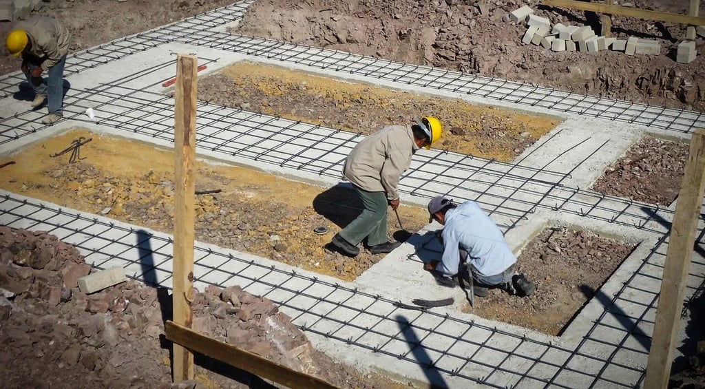
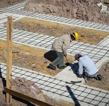
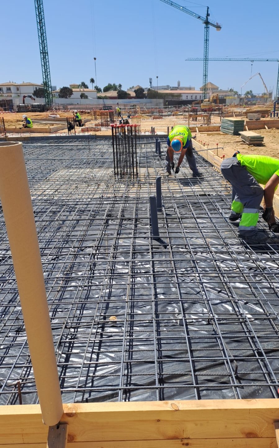
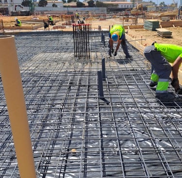
Placing reinforcing steel
Placing the reinforcing steel must meticulously follow the structural design, focusing on continuity, concrete cover, and the correct joining of the pieces.
1. Steel in Footings and Foundation Slabs
Footings and slabs are the elements that distribute the house's weight into the soil. The steel here is mainly placed in the form of mats or grids.
a. Assembling the Steel Mat
Direction: The steel bars (rebar) are placed forming an orthogonal grid, with steel in both directions (longitudinal and transverse). The steel's diameter and spacing are defined by the structural calculation.
Mat Position: In isolated footings and shallow slabs, the steel is generally placed in the bottom layer (bottom chord), as this is where the greatest tension stresses occur due to flexure (the soil pushes upward).
Tying: The rebar is securely tied at every intersection using annealed wire (known as tie wire). The tie must be strong enough to maintain the geometry during the concrete pour but does not need to be welded, unless specifically indicated by the design.
b. Minimum Concrete Cover
This is the most critical detail for durability. The concrete cover is the distance between the outside edge of the rebar and the surface of the concrete.
Purpose: To protect the steel from corrosion (rusting) caused by ground moisture. Rust causes the steel to expand, cracking the concrete.
Ensuring Cover: Spacers or chairs (prefabricated concrete, plastic, or metal pieces) must be used at the bottom. These elements lift the steel mat off the blinding layer (plantilla), ensuring the minimum cover (typically between 5 and 7.5 cm or 2 to 3 inches when in contact with the soil).
2. Steel in Grade Beams (Foundation Beams)
Grade beams are structural beams that connect the footings, helping the foundation work as a single unit and distributing loads.
Longitudinal Steel: Continuous bars are placed along the beam (at the top and bottom) to absorb flexural and tension forces. It is crucial to respect the correct laps (joining lengths) if the beam is longer than commercial rebar lengths.
Stirrups (Ties): These are closed steel rings placed perpendicularly to the longitudinal steel.
Function: They resist shear forces and confine the concrete, increasing ductility and strength.
Placement: The spacing of the stirrups is tighter (closer together) at the ends of the grade beam (support zones) and may be wider in the center.
3. Starter Steel for Columns and Masonry Walls
The foundation steel must have continuity with the vertical structure it will support (columns or load-bearing walls).
a. Starter Bars or Anchors (for Footings and Slabs)
Column Starters: The column bars must project from the footing's steel mat. These bars are bent in an L-shape and tied to the footing's mat. This connection transfers the column load to the foundation.
Development Length: The starter bar or "L-bar" must have a sufficient length (development length) to ensure the bar will not pull out of the concrete when the structure is under tension.
b. Placing Vertical Steel in Grouted Cells (Reinforced Masonry)
In houses that use concrete block or brick walls as the load-bearing structure, the vertical reinforcement is placed inside the block's cells or hollows.
Preparation: Before starting to build the wall, starter bars must be left projecting from the foundation at the location of each structural cell.
Continuous Vertical Rebar: As the wall is built, the vertical rebar (of the indicated diameter and quantity) is inserted or extended within the cell.
Cell Grouting: Finally, the cells containing rebar are filled with a fluid concrete (grout or fill mortar) that encapsulates the bar and joins it monolithically to the foundation and the upper tie beams. This rebar is the wall's tension reinforcement and is vital for seismic resistance.
Constant supervision by an engineer is crucial to validate that the steel's diameter, spacing, cleanliness, and concrete cover strictly comply with the structural drawings.
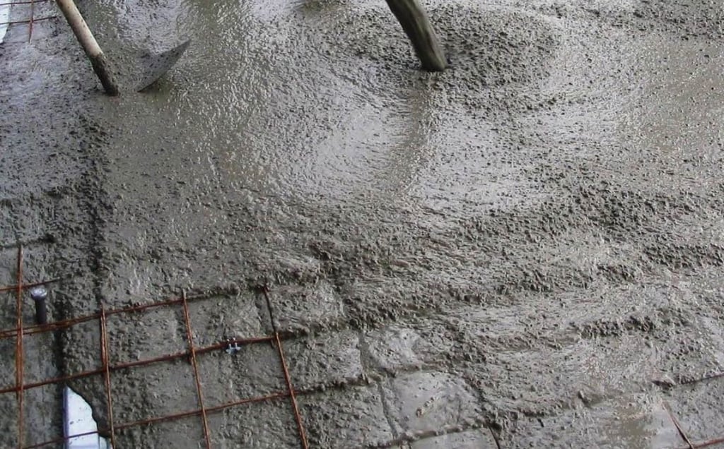

Concrete pouring
The success of concrete pouring depends on good preparation, the correct choice of material, and careful execution to achieve maximum compaction.
1. Pre-Pour Preparation
Before the first mixer truck (or "drum") arrives, the job site must be completely ready to avoid delays, as concrete has a limited working life before it cures.
Final Inspection of Formwork and Steel: The supervisor must verify that the formwork is clean, stable, and well-braced to resist lateral pressure. Furthermore, they must check that the reinforcing steel is correctly placed, tied, and, fundamentally, that the spacers (chairs/blocks) guarantee the minimum concrete cover.
Surface Cleaning: The inside of the formwork and the bottom of the excavation must be free of soil, debris, or puddles of water.
Wetting: In hot climates or to prevent wooden formwork from absorbing water from the concrete, it's recommended to wet the internal surfaces of the formwork and the blinding layer. However, there must be no standing water.
Pouring Plan: The route of the trucks, the location of the pump (if used), and the order of filling the footings and grade beams are defined.
2. The Right Concrete Mix
The concrete mix is a critical specification.
Strength and Mix Design: The concrete must have the specified compressive strength (f′c) from the plans (commonly 200 to 250 kg/cm2 or higher for foundations).
Slump Management: The slump (a measure of concrete flowability) must be appropriate for placement. For foundations, a low to medium slump is generally used, as the concrete shouldn't be excessively liquid but manageable enough to flow around the reinforcing steel.
Admixtures (Optional): Additives can be used to improve workability (making it easier to handle), to retard or accelerate curing (depending on the climate), or to make it more water-resistant.
3. Pouring and Compaction Process
The key to strength lies in compaction: the elimination of trapped air.
Controlled Pouring: Concrete should be placed as close as possible to its final position. Avoid dropping it from great heights (more than 1.5 meters or 5 feet) to prevent segregation, which is the separation of components (the aggregate separates from the cement paste).
Placement in Layers: In deep trenches or pits, the concrete is poured in continuous, horizontal layers, without letting one layer cure before the next is poured.
Use of a Vibrator: Mechanical compaction with an internal vibrator is mandatory. The vibrator is inserted vertically into the fresh concrete and slowly withdrawn, ensuring the material fills all spaces, especially under the rebar and in the corners, eliminating air.
Warning: Excessive vibration causes segregation, leading the cement paste (the fines) to rise and the heavy aggregates to settle. Vibration should be brief and done at multiple points.
Cell Grouting: If block cells are being filled for vertical reinforcement, a more fluid concrete (grout) must be used to ensure it completely fills the void and perfectly surrounds the rebar.
4. Curing and Post-Pour Protection
Curing is the most neglected stage and often the most important for long-term strength.
Curing is Hydration: Concrete needs moisture and controlled temperature for the cement's chemical reaction (hydration) to continue and reach its maximum strength.
Moisture Maintenance: Once the surface begins to harden, it must be kept moist for at least the first 7 days. This is achieved in several ways:
Constant wetting or spraying with water (the most common method).
Covering the surface with plastics, tarps, or wet burlap.
Applying curing membranes (chemical products that seal the surface).
Protection: The concrete must be protected from rapid evaporation (sun and wind) which can cause surface cracking, and from heavy rain which could wash away the cement or erode the surface.
Curing Time: Although the formwork can be removed in 24 to 48 hours (stripping the forms), concrete reaches its final design strength (f′c) at 28 days. Significant structural loads should not be applied until a safe period has passed, as per the design.